Development of a Small Scale Wavemaker
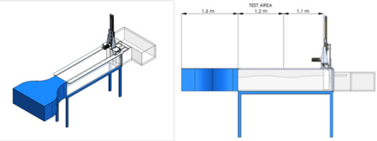
After recent mechanical upgrades, the small scale wavemaker is being reinstalled in the flume tank at UVic. It now features a new larger actuator and a reinforced structure to improve the rigidity of the device. The system will allow small scale WEC concepts to be tested conveniently on campus. In addition, the tank will be used to validate numerical models by comparing to test cases such as breaking waves and overtopping over a fixed deck.
The current objective of the wavemaker is to accurately generate regular, irregular and focused waves. The motion of the wavemaker piston is calculated based on linear wavemaker theory described by Robert G. Dean and Robert A. Dalrymple (1984): ‘Water Wave Mechanics for Engineers and Scientists’. For irregular waves or other waveforms with multiple spectral components, piston motion will be calculated as described by Ivan Miskovic et al. (2008): ‘Wavemaker Control System for Irregular Developed Sea Waves Generation’.
To evaluate the performance of the wavemaker, regular waves will be generated using open loop control over a range of wave heights and frequencies within the intermediate and deep water regimes. The piston motion will at first be sinusoidal, however secondary waves may be an issue when generating large amplitude waves. Therefore it may be necessary to calculate more complicated motion profiles so that the piston motion matches the horizontal motion of water particles underneath the wave.
The performance of irregular wave generation will also be evaluated by comparing the shape of the measured wave spectrum to the commanded spectrum. Accuracy of the focused wave is less important so long as the wave train converges to form a large wave within the test area. The focused wave will be created by generating multiple waves with varying celerities so that the peaks of each wave converge to form a larger wave.
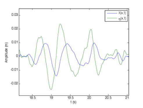
Closed loop control may need to be implemented to absorb wave reflections and remove unwanted waves generated from the wavemaker mechanism. The two possible methods are force feedback and position feedback. Force feedback is more commonly used in industry and detects reflections by measuring the force applied to the wavemaker piston. However this method may be infeasible since waves generated behind the piston will contaminate the force measurements. Position feedback uses two wave probes, one positioned in the test area to measure the generated wave and another at the wavemaker piston to measure wave height and detect reflected waves. This method will likely be used as it is simple to implement and is not affected by waves behind the piston.